Decoding Block Diagram.
Today, we can almost decode anything with the help of a computer. But how do you do that? On this page I will share the techniques to decode received signals. Most of them are used to decode satellite telemetry but they can also be used for other purposes. Because a picture is worth a thousand words I made the below diagram to support the explanations.
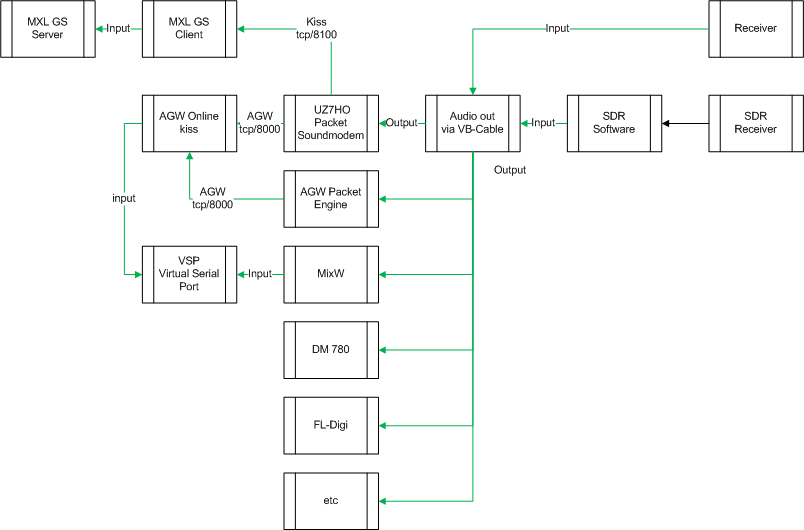 Figure A: Decode Block Diagram
From RF to audio
On the right side RF signals are coming in from your antenna setup and are being fed to your receiver. These can be traditional or software defined receiver. The first challenge, is to feed the demodulated signal into an other application. If you are using a physical receiver make sure you connect the audio output of that receiver via a galvanically isolated connection to the input of your computer.
With physical receivers you must remember that you won’t be able to decode all signals, this has to do with the IF and/or audio bandwidth. For example in a standard configuration a 9600bps FSK packet signal is to wide and can’t be decoded in this way, keep this in mind.
With software defined radios we don’t have this limitation because there is a possibility to change this within the software. One thing we do have to keep in mind, and that is the audio sample-rate determines the maximum usable frequency.
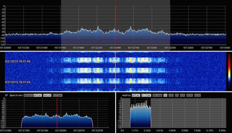 Figure B: SPROUT Satellite AFSK 1200bps (SDR# + IF Processor + Sound Processor plugin)
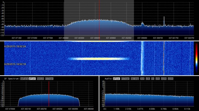 Figure C: GRIFEX Satellite FSK 9600bps (SDR# + IF Processor + Sound Processor plugin)
So when you run into issues when you’re trying to decode high bandwidth signals, make sure the sample-rate is high enough. As an example, SDR# has a default sample-rate of 32000 this can be to low for high speed packet (9600-19200bps FSK) this can be changed by editing the SDRSharp.exe.config file. Search for <add key=”minOutputSampleRate” value=”32000″ /> and change the value to for example 44100 or even 48000 it depends on what you want to decode.
From audio to decoding
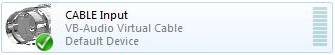 Now that we have a audio signal that can be used as an input to the different decoders we have to find a way to connect it to that decoder. In the physical world you could just put a connector in a device but with software this isn’t possible. To solve this we have to use a program that can do this for us. There are multiple options (also see the my sound-modem page) but in this example I will use VB-Cable. This solution can be downloaded and installed and will present it self as an extra input and output audio device
 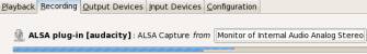 when you are running a Windows operating system. On Linux one can achieve the same with for example Pulse-audio Volume Control. To use this new device and be able to redirect the audio output from your receiver you have to select the VB Cable input and select this as output device within your SDR software. (A physical connection from a RX can also be connected via for example line-in or mic-in) When this is done the VB-Cable output can be selected as an input for the decoder program.
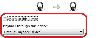 I can imagine that you want to listen to the signal which is offered by your receiver, you can achieve this by enabling the “listening to” via the audio control configuration screen. Be careful not to create a loop by selecting the wrong device.
When everything is connected and configured in the right way, you can see decoded data within the program you are using. In the case this program is a software modem, you will have to read on.
From Audio to program (decoder)
In figure A you see a number of programs where you can feed the output of VB-cable to the input of the program and doesn’t need further software to get a result. For example you can decode CW/Morse with FL-Digi and read the decoded output in the monitor screen.
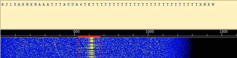 Figure D: FL-DIGI – HO-68 morse
From Audio to Sound-Modem (AGW, UZ7HO or MixW)
With the three packet sound-modem examples this is also the case when operating in TNC mode. In this mode al the decoding is done within the (software) TNC (only UI frames) and no further decoding has to be done.
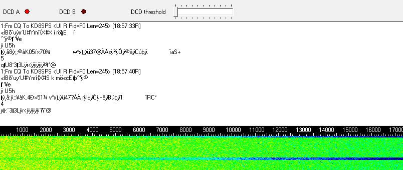 Figure E: UZ7HO HS Sound-Modem – GRIFEX 9600bps data
But when this communication is KISS based, another software program needs to receive the data and process the information. For this purpose I use AGW Online Kiss. When telemetry is transmitted as a KISS stream the data can’t be decoded by AGW PE. This is where the AGW Online Kiss program comes in. The received data by AGW PE is displayed as a hex dump and stored as corresponding KISS file. The connection between AGW PE or UZ7HO is done via a tcp socket that default listens on port 8000, this port is openend when AGW PE or UZ7HO is started. (The first time when the program is started the Windows firewall will ask you to allow or deny the opening of the tcp/8000 port)
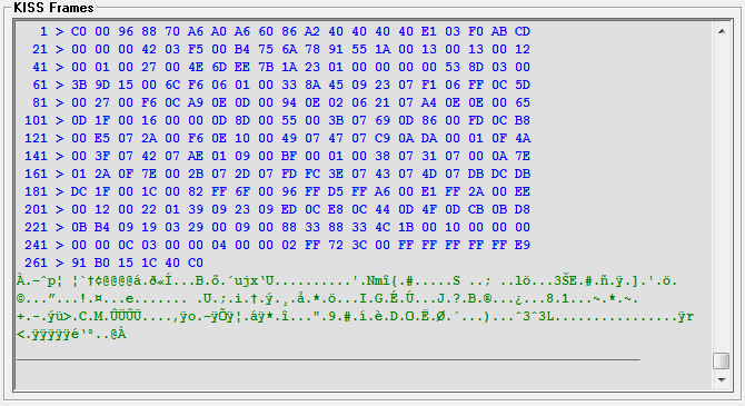
Figure F: AGW Online Kiss – GRFIEX HEX Kiss frame.
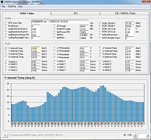 After the pass you can use one of the telemetry decoders from DK3WN. Make sure to read the requirements before you start using these decoders when the dependencies are met, start the program and open the stored KISS file to produce the output.
From Audio to Sound-Modem (Kiss)
The Sound-Modems from UZ7HO have beside a AGW output also a Kiss output, default this options is disabled but under devices you can enable this Kiss port (default on tcp/8100). The Kiss port gives you the option to connect a program that can operate directly with Kiss data. An example is the GRIFEX Ground Station client from MXL. This software is made around python and would require you to install a python run-time to connect a physical TNC via serial port. After that the software creates a serial to tcp session to connect the kiss data from the TNC to the real Ground Station client. With UZ7HO and the Kiss port enabled you can skip to serial to tcp configuration. Instead you can connect the GS client directly to UZ7HO. Below the configuration.
Go to the following directory %DIR%\GRIFEX\GS\groundstation and edit config.props. In my case the Kiss port is running on 9100 and not the default 8100.
radio.1.name=Radio
radio.1.address=localhost
radio.1.port=9100
radio.1.type=KISS
radio.1.tncport=1
If you configured the client with the right credentials then every time a frames is received and decoded it is automatically forwarded via the internet to the MXL dataserver and in this way you support the team real-time.
From Audio to Sound-Modem (Serial)
What if the software you want to use only has an option to connect via serial? Especially older software only has an option to connect via serial port, in those days there where no ways to connect via other methods. So is it possible to connect such a program? Yes there is. We are going to configure a serial bridge. In Figure A there are two options that support this and both need an additional piece of software. This software is generally called VSP Virtual Serial Port and most of the time creates a software null-modem cable. On one end of the cable you can connect software like MixW or AGW OnLine Kiss (via mirror option) and on the other end the program you want to use with only serial support.
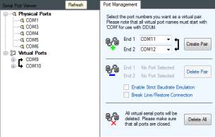 In this example I use VSP Manager from K5FR after requesting the software and installing it, you can create virtual ports. In the example on the right you can see that I created a virtual cable with COM9 on one end and COM10 on the other.
Now when I configure the AGW Online Kiss mirror function (this is done via the agw_onlinekiss.ini file) to use COM9 all received (kiss) frames are mirrored to COM10. Now the only thing that remains is to configure the software with only serial support to connect to COM10. This options can also be used with MixW.
Combine all the software and you could get something like the following YouTube video shows you. Thanks to K4KDR.
June 29, 2015 version 0.1 – Initial setup.
June 29, 2015 version 0.2 – Sound-Modem updates.
June 29, 2015 version 0.3 – Serial connections via sound-modem.
June 29, 2015 version 0.4 – Ground station software.
April 04, 2016 version 0.5 – YouTube movie putting it all together by K4KDR, remarks and question are welcome.