S-band reception
This band is used for Space to Earth transmission and most of the traffic is either CW, PSK or spread spectrum.
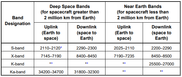
NASA Allocated Frequency Bands:
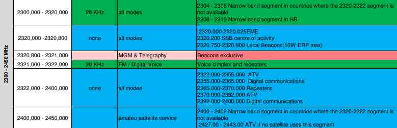
IARU 13 cm range is from 2400.000 – 2450.000 MHz and 2400 – 2403 is used for narrow band modes (WiFi channel 1 is at 2412).
Considerations:
When trying to receive weak signals within this band one needs to realise that for example the 2.4GHz range is used by WiFi and that this can have a negative influence on the reception.
2.4 GHz WLAN/WiFi Technology (802.11 b/g/n) uses the frequency band from 2401 to 2484 MHz. This bandwidth is divided among 14 channels. Each of the WLAN / WiFi Channels are spaced 5 MHz apart, except the last two channels which are spaced 12 MHz apart. Most of these channels (Channel 1 to Channel 11) can be used across the globe, except channels 12, 13 and 14. Channel 12 (2456 – 2478 MHz) and Channel 13 (2461 – 2483 MHz) are not allowed in North America, whereas Channel 14 (2473 – 2484 MHz) can only be used in Japan.

Band pass (cavity) filters: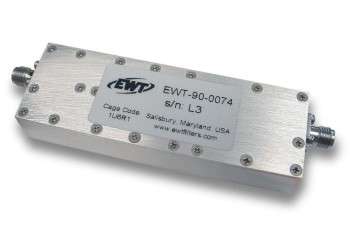
It seems that if one wants to be successful with reception of S-band signals, a good band pass filter is a must. Signals for example from Wi-Fi systems can make it impossible to receive weak signals.
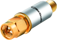 Mini circuits example: VBF-2275+ LTCC Band Pass Filter, 2170 – 2380 MHz, 50Ω
Coax attenuation:
When trying to receive higher frequencies the attenuation of the coax cable used is also a variable to take into consideration.
Here is an overview of the most used coax cables, the table shows the attenuation per 100 meters.
| Attenuation dB / 100 m | |||||||||||||
| Type f/MHz: | 10 | 30 | 50 | 100 | 145 | 200 | 400 | 435 | 500 | 1296 | 2320 | 3000 | 5000 |
| RG-11 AU | 2,2 | 4,0 | 7,5 | 11,0 | 19,0 | 60,0 | |||||||
| RG-55 | 16,0 | 29,0 | 52,0 | 77,0 | 90,0 | 127 | |||||||
| RG-58 CU | 4,6 | 8,0 | 11,0 | 16,3 | 20,0 | 24,0 | 36,0 | 40,0 | 47,0 | 90,0 | 140 | 180 | 272 |
| RG-142 AU | 7,0 | 9,0 | 14,0 | 15,0 | 20,0 | 28,0 | 30,0 | 35,0 | 49,0 | 72,0 | 95,0 | 128 | |
| RG-174 U | 12,0 | 17,0 | 29,0 | 34,0 | 45,0 | 55,0 | 60,0 | 70,0 | 110 | 175 | 220 | 325 | |
| RG-188 AU | 12,0 | 17,0 | 28,0 | 32,0 | 40,0 | 58,0 | 68,0 | 113 | 165 | 268 | |||
| RG-196 AU | 22,0 | 27,0 | 43,0 | 62,0 | 95,0 | 102 | 300 | ||||||
| RG-213 U | 2,0 | 3,6 | 4,3 | 6,3 | 8,2 | 9,5 | 14,5 | 15,0 | 17,0 | 26,0 | 55,0 | 89,0 | |
| RG-213 US-100 | 1,8 | 2,45 | 3,2 | 5,9 | 10,1 | 21,1 | |||||||
| RG-214 US | 1,8 | 3,2 | 3,9 | 5,7 | 7,6 | 9,0 | 13,0 | 15,0 | 23,5 | 45,0 | |||
| RG-223 U | 4,0 | 7,0 | 13,0 | 18,5 | 20,0 | 30,0 | 34,0 | 38,0 | 60,0 | 85,0 | 100 | 151 | |
| RG-316 U | 12,0 | 17,0 | 28,0 | 32,0 | 40,0 | 58,0 | 68,0 | 113 | 165 | 268 | |||
| H100 | 2,1 | 2,8 | 4,9 | 8,8 | 16,0 | 23,0 | |||||||
| H155 | 3,1 | 3,4 | 6,5 | 9,4 | 11,2 | 19,8 | 21,9 | 34,9 | |||||
| H500 | 1,3 | 2,9 | 4,1 | 8,7 | 17,4 | 24,1 | |||||||
| Aircom-plus | 0,9 | 3,3 | 4,5 | 7,4 | 7,5 | 14,5 | 21,5 | 25,0 | 34,1 | ||||
| Aircell-7 | 3,7 | 4,8 | 6,9 | 7,9 | 14,1 | 26,1 | |||||||
| CF1/4″Cu2Y | 2,5 | 5,5 | 9,0 | 18,0 | |||||||||
| CF3/8″Cu2Y | 1,6 | 3,8 | 6,5 | 13,0 | 16,0 | ||||||||
| CF1/2″Cu2Y | 1,2 | 3,0 | 5,6 | 10,0 | |||||||||
| CF5/8″Cu2Y | 1,0 | 2,5 | 4,0 | 7,2 | 10,0 | ||||||||
| TU-165 | 29,0 | 41,0 | 120 | ||||||||||
| TU-300 | 17,0 | 25,0 | 75 | ||||||||||
| TU-545 | 9,0 | 14,0 | 45 | ||||||||||
| 4/S-60 | 2,0 | 4,0 | 7,0 | 19,0 | |||||||||
| 60-7-2 | 2,0 | 7,0 | 10,0 | 17,0 |
Antennas:
Helical 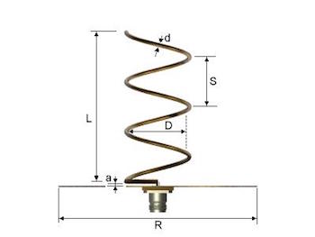 antennas are the most widely proposed antennas in satellite communications systems. The main reason why these antennas are used in satellite and space communications is circular polarisation. Good axial ratio provides precise measurement of the polarisation of the received signal due to immunity of the circularly polarised wave to Faraday rotation of the signal propagating through the ionosphere.
Online helical antenna calculators:
Patch, Yagi
Pre Amplifiers:
To overcome the cable loss especially on higher frequencies one can install a Low noise amplifier. Below an example from Kuhne. But you can also use a LNA4ALL there are some stations that use this with good result. Keep in mind that it could be that the amplifier filtering is narrowing the bandwidth that you can use.
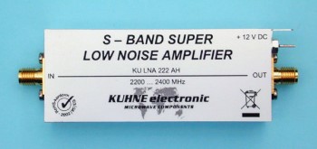 Kuhne KU LNA 222 AH, Super Low Noise Amplifier.
- Frequency range 2200..2400 MHz
- Noise figure @ 18 °C typ. 0.5 dB, max. 0.6 dB NF
- Gain typ. 30 dB
- Maximum input power 1 mW
- Output IP3 typ. +27 dBm
- Supply voltage +9 … 15 V DC
- Current consumption typ. 80 mA
- Operating case temp. range -40 … +65 °C
- Input connector / impedance SMA-female, 50 ohms
- Output connector / impedance SMA-female, 50 ohms
Reception setup:
Direct reception with for example a SDR receiver that has a range into the GHz frequencies, there are multiple examples and currently we see a lot of Pluto and Ettus receivers being used. The challenge will be how to minimalize the cable loss from antenna to receiver.
Pluto SDR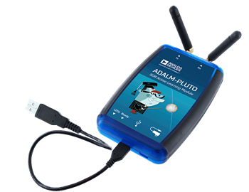
- Based on Analog Devices AD9363–Highly Integrated RF Agile Transceiver and Xilinx® Zynq Z-7010 FPGA
- RF coverage from 325 MHz to 3.8 GHz
- Up to 20 MHz of instantaneous bandwidth
- Flexible rate, 12-bit ADC and DAC
- One transmitter and one receiver, half or full duplex
- USB 2.0 Powered Interface with Micro-USB 2.0 connector
Ettus B200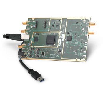
- The first fully integrated USRP device with continuous RF coverage from 70 MHz to 6 GHz
- Full duplex operation with up to 56 MHz of real time bandwidth (61.44MS/s quadrature)
- Fast and convenient bus-powered connectivity using SuperSpeed USB 3.0
- GNURadio support through the open-source USRP Hardware Driver™ (UHD)
- Early access prototyping platform for the Analog Devices AD9364 RFIC, a fully integrated direct conversion transceiver with mixed signal baseband.
Down converter reception:
Kuhne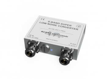
- Frequency range (RF) 2000..2700 MHz
- Maximum input power 1 mW (0dBm)
- Frequency range (IF) 160..860 MHz
- Noise figure @ 18 °C typ. 0.8 dB, max. 1.0 dB
- Gain @ 25 °C typ. 35 dB
- Output IP3 25 dBm
- LO frequency 1840 MHz
- LO accuracy @ 18 °C +/- 2 ppm
- Supply voltage +9 … +36 V DC
- Connectors / impedance N-female, 50 ohms
Build ideas:
Looking for, help wanted with:
Surplus hardware information and places where it is being sold. Please respond via the contact page if you can share information.
Information sources:
UHF Satcom: Also visit this site if you are looking for frequencies.
Kuhne Converters: Low noise down converters in the RF and microwave frequency bands.
LNA4ALL: Low Noise Amplifier from 28 MHz to 2500 MHz.
High Sierra: Converters with 10 MHz external reference.
Riddles in the Sky: A blog dedicated to observing satellites.
NASA JPL: Frequency and Channel Assignments.
A new golden age of Radio: Development tools for Software Defined Radio.
The Unified S-band system is a tracking and communication solution.
DSN Link Design: Handbook.
June 4, 2020 version 1.0 – Initial setup.
June 5, 2020 version 1.1 – feedback updates.
June 8, 2020 version 1.2 – feedback updates.
June 14, 2020 version 1.3 – feedback updates.
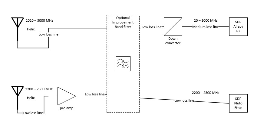
June 17, 2020 version 1.4 – added a block diagram.